RF Support
Manuals & Methods
Top Five FAQs
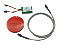
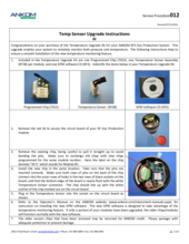
There may be a problem with the radio frequency (RF) chip attached to the circuit board. This is a dark green/blue colored chip with a black antenna. Refer to RF Service Procedure Chip and Board Replacement (RFS013) for help in identifying the part.
To diagnose, perform the following steps:
- With the GPM program running, identify a module that is communicating normally.
- Unplug and remove the batteries from a working module and the module that is not working.
- Shut down and restart the GPM program.
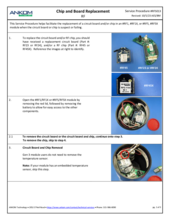
- Remove the RF chip from both modules, being careful to avoid pulling on the antenna.
- Switch the RF chips by plugging the RF chip from the working module into the non-working module’s circuit board and the RF chip from the non-working module into the working module’s circuit board.
If the original working module is no longer working and the original non-working module is now working, this indicates that the RF chip needs to be replaced. Unplug the batteries and return the RF chips to their respective modules.
If the original working module is still working and the original non-working module is still not communicating, this indicates the RF circuit board needs to be replaced. If neither module works, this indicates that both the RF chip and the circuit board need to be replaced.
Contact ANKOM Technology for a replacement RF chip (Part #: RF45/#RF45X) and / or an RF circuit board (Part #: 7007). Provide the RF chip number and the network number of your RF Gas Production System when contacting so that the RF chip is programmed properly. The network number could be any of 1-5 and is noted in the upper right corner of the ANKOM sticker on the Base Coordinator (Part #: RF2) on the line following the "N". Refer to RF Service Procedure Chip and Board Replacement (RFS013) for installation directions.
First, be sure Synthetic Grease w/PTFE (Part #: RF41) was used on the lip of the bottle and the lip of the septa port on bottles so equipped. This aids in making a tight seal. Second, inspect the gasket which seals the module top to the bottle. It is important to do this before each run starts. If the gasket is loose, has slid to one side, or is showing signs of wear and deterioration, replace the gasket. Reference RF Service Procedure Gasket Replacement (RFS011). After inspection and, if necessary, replacing the gasket, test the module per RF Service Procedure Module Testing (RFS001).
Refer to RF Service Procedure Module Testing (RFS001).
First, check the pressure within the module. If the pressure is approaching 10 psi, stop using this module and unscrew the module top immediately to avoid over-pressurizing the bottle.
If the bottle is at a safe pressure (<10 psi), confirm that the "Global Release" Set button has been clicked. If a number is only typed in the "Global Release" box and the "Set" button has not been clicked, your desired global release setting will not be populated into the "Pressure Release" fields below each module # column. In this case, valves will not open to release pressure to your desired setting. Click "Set" if needed.
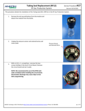
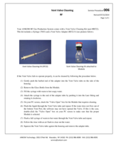
It may be that the exhaust tube is stuck from either lack of use or from condensation of the content that was in the bottle. While twisting back and forth the exhaust tube, gently pull on the tube to see if it is stuck shut. If this causes pressure to release, then execute the vent valve cleaning procedure detailed in RF Service Procedure Vent Valve Cleaning (RFS006) listed in the documents below.
Also, be sure the battery is not in the yellow range (6.29-6.00 volts) or red zone (<6.00 volts). It is possible that in the lower end of the yellow and in the red voltage range the battery will have enough power to communicate but not enough to open the valve; change the battery.
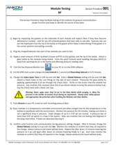
If this does not solve the problem, listen for the solenoid faintly clicking (this will occur once every 15 seconds as the solenoid opens the valve). If it is clicking, but no pressure is releasing then the valve is stuck closed. Remove the module from the test and contact ANKOM Technology at www.ankom.com/contact/technical-services or call (315) 986-8090 for module repair.
If no clicking sound is audible, the solenoid may have been partially unplugged from the circuit board. The solenoid has two thin white wires going to a small white 2-pin connector on the circuit board. Make sure the connector is securely plugged in and that the wires are not loose. If this does not resolve the problem, there may be a problem with the circuit board or the solenoid. Remove the module from the test and contact ANKOM Technology for module repair.
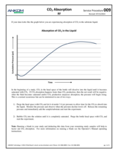
Refer to RF Service Procedure CO2 Absorption (RFS009).
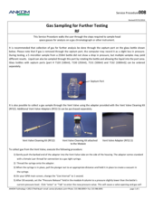
Refer to RF Service Procedure Gas Sampling for Further Testing (RFS008).
Troubleshooting? Let us help!
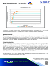
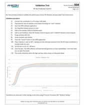
For the most efficient and quick way to determine if your RF Gas Production System is operating correctly, run a validation test. If the results appear inconclusive, submit your results to our analytical team.
Parts & Consumables
Browse the RF Product Catalog for associated parts and support items
RF Maintenance Kit
Items needed to keep your RF Gas Production System operating smoothly
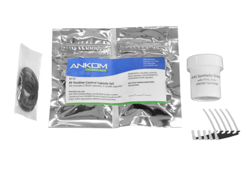
Instrument Performance Test
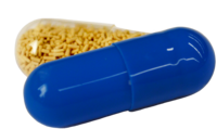
Positive Control Capsules ensure proper instrument function and correct procedural technique
SDS Sheets
View associated product documentation and safety information

Service Procedures

How can we help?
Don’t see what you need on this page?
Search for a specific topic to search all resources.