Instruments
Product Categories
Resources
The solenoid will become hot if the valve open check box is left checked. Normal valve openings are very brief and within a range of 10-1000 milliseconds, which does not cause the solenoid cylinder to get hot. If the Open Valves button is clicked or...
The sensors are accurate to within +/-2°C over a range of 5°C - 60°C. To account for any Module-to-Module differences in temperature sensing capability, the GPM software provides a calibration screen that can be used before data recording begins...
Possible Causes: (1) The bag suspender is worn or not properly functioning. Refer to Service Procedure Bag Suspender Check (DES006). (2) The vessel is overfilled with solution. (3) The level sensor is not detecting the solution. To service the blue...
You must run GPM software version 9.7 or greater when operating modules with temperature sensors.
The auto-graphing capability provides the user with a visual indication of the data being recorded during a gas study. However, the graphs themselves are NOT automatically stored after the study is complete. There are three ways to save the graphs...
This is most likely because the default AutoSave location is in a location that your computer may not have "write" access to. In addition, behind the scenes, the program is also attempting to save a log file of every communication between the...
Yes, the Dual Lead Rechargeable Battery ( Part #: RF46) allows you to connect the battery to both the module and the charger while the module is in use. Place the dual lead battery in the module and connect one lead to the module and the other to the...
Fifteen RF modules with 100-500ml size bottles attached will fit in the 20-liter Water Bath (Part #: WB20SH or WB20ISH). Eight RF modules with 1-liter bottles attached will fit in the 20-liter Water Bath (Part #: WB20SH or WB20ISH).
Possible causes include: A loose or disconnected wire from the pressure sensor A faulty circuit board To diagnose, unplug the pressure sensor connector from the circuit board and plug in a pressure sensor connector from a working module into the same...
The pressure sensors are accurate to +/-0.04 psi. Fluctuations in cumulative pressure beyond this correspond to either a leak or a fluctuation in temperature when a module is attached to a sealed bottle. If you check the "valve open" check box, leave...
There may be a problem with the radio frequency (RF) chip attached to the circuit board. This is a dark green/blue colored chip with a black antenna. Refer to RF Service Procedure Chip and Board Replacement (RFS013) for help in identifying the part...
Typically, a fully charged rechargeable battery (Part #: RF16 or RF46) should be able to power a module for approximately ten days under normal conditions (20°- 40°C GPM settings of 60-second Live Interval and one valve opening sequence per hour.) As...
The vessel temperature has exceeded the maximum limit. Possible Causes: The solution level is low in the vessel, but the level sensor is indicating full. The level sensor has two main components that work together. These components are a Level Sensor...
Refer to RF Service Procedure Gas Sampling for Further Testing (RFS008).
Please refer to Appendix E of the Operator's Manual.
The volume of "dead space" between the vent valve and the septum on an RF module is .003 cubic inches for the RED capped modules, and .043 cubic for the BLACK capped modules.
Refer to RF Service Procedure CO2 Absorption (RFS009).
Possible Causes: Motor wires are loose or disconnected. Unplug the instrument. Inspect the wiring to the motor. Contact ANKOM Technology if a loose or disconnected wire is found. If the wires are intact, run this test: Turn the instrument on and...
To ensure that the controller settings are correct, refer to A200 Service Procedure Controller Reset Procedure (FS002) for instruments purchased pre-9/03, or, see A200 Service Procedure Controller Menu Setup (FS001) for instruments purchased post...
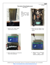
For illustrations of melted trays, see A200 Service Procedure Temp Probe Replacement (FS016). Bag suspender trays can melt when there is not enough solution in the vessel to cover all of the trays while the instrument's heat is activated. Possible...
When the pressure in the vessel is too high, the pressure switch will turn off the heater. Possible Causes: There is too much solution in the vessel. Make sure two liters or less of solution is used in the vessel at a time. The motor is not turning...
Refer to Service Procedure Agitation System Check (DES031).
Possible Causes: The solution temperature has exceeded the maximum limit. Perform the boil test detailed in Service Procedure Boil Test (AS013).
The instrument is experiencing a high-temperature fault. If your controller is set to 100°C, there are two possible reasons for this fault. (1) The agitation is not working properly during an assay. To check the agitation during an assay, remove the...
The instrument is experiencing a pressure fault. There are three possible reasons for this fault. (1) More than 2 L of solution was in the vessel during the digestion process. A pressure fault will most commonly occur if there is more than 2 L of...
First, make sure that your Daisy is not placed under an Air Conditioner or fan. Check your Daisy instrument bulbs, controller, and temperature probe to ensure they are functioning properly. With further questions or concerns, please contact ANKOM...
This is likely due to a valve that may be "stuck" closed. If the instrument has not been used in a while, it is possible that the solution is simply to clean the valves and clean any debris or buildup that may have settled on the valve piston. To...
For XT10, see Service Procedure Fault ETS (X0S002). For XT15, see Service Procedure Fault ETS (X5S016).
There is a leak. The most common cause is a leaky Q1 valve, which would cause cooling water to flow into the vessel during the heating stage. To test: Turn the instrument completely off but keep the water supply on. Check to see if water is running...
The drain valve has been told to open, but after 30 seconds the drain-open switch has failed to open the drain. Possible Causes: (1) The wires on the drain valve have become disconnected. Unplug the instrument, check the drain valve, and reattach any...
Part #
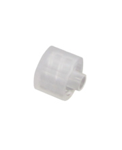
The 7147 Male Luer Cap is used to close off the end of the Female Luer Port ( Part #: 7146) or the Luer Duckbill Check Valve ( Part #: 7139).
Part #
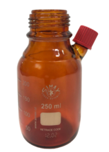
LIMITED STOCK AVAILABLE. ANKOM provides many different bottles that can be connected to an RF1 Gas Production Module within the RF Gas Production System. The 7154 bottle provides the following features: - up to 250ml of space to hold analysis...
Part #
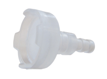
This filter prevents solid material from entering the instrument through the fluid container.
Part #
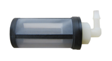
This filter prevents solid material from entering the instrument through the fluid container.

Part #
The Black Nitrogen Supply Tubing is used as a replacement part for cracked or damaged nitrogen supply tubing or where additional length is required. The unit price is per foot. Please specify the length in the quantity field when ordered.
Part #
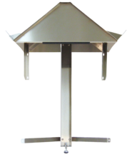
This shelving assembly provides a turn-key system for holding chemical cubitainers at the correct heights for use with the A2000 Automated Fiber Analyzer. For installation instructions, refer to Service Procedure Cubitainer Shelf Installation (AS024)...
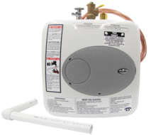
Part #
This water heater, 120v can be used with the DELTA/DELTAI and A2000/A2000I Fiber instruments. It provides the required hot rinse water for DELTA/A2000 operation. If you have a 220v connection, you will need to connect this water heater to a Voltage...
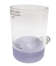
Part #
Amylase is used for liquification of starch during Neutral Detergent Fiber analysis. This A03 amylase container connects to the A2000 instrument and is used for dispensing amylase into the A2000 during the rinse cycle.
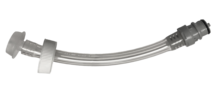
Part #
If you are using cubitainers for your fiber analyses, the chemicals must move from the cubitainers to the instrument. This tubing connects a cubitainer to port A or B to deliver chemicals to the instrument.
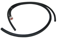
Part #
This hose provides a safe way to drain the A2000 to the proper exhaust.
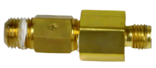
Part #
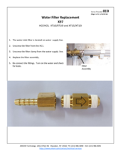
The Water Filter Assembly is found in the DELTA/DELTAI and A2000/A2000I Fiber instruments. It is necessary to filter the water before it enters the valves.
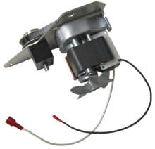
Part #
The A08 Motor Assembly 120v, drives the agitation system in the 120v DELTA & A2000.
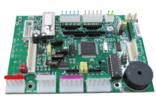
Part #
This is the internal computer that controls the A2000 Fiber Analyzers.
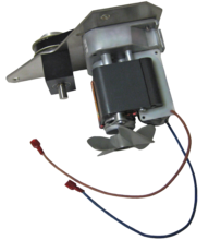
Part #
The A10 Motor Assembly 220v drives the agitation system in the 220v DELTAI & A2000I.
Part #
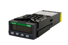
The Temperature Controller is used in the DELTA/DELTAI and A2000/A2000I Fiber instruments and maintains vessel temperature during digestion.
Part #
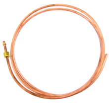
The Copper Water Supply is used to connect the DELTA/DELTAI and A2000/A2000I instruments to the user's water source.
Part #
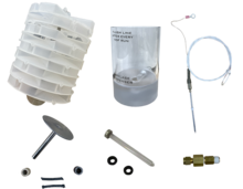
This replacement package contains the following parts: Amylase Container Assembly ( Part #: A03) Water Filter Assembly ( Part #: A07) Temperature Probe Assembly ( Part #: A17) Bag Suspender w/ weight ( Part #: F11) Agitator w/ Packing Set ( Part #...