Log in/Register
  • Create new account
  • Request new password
  • Home
  • News
  • About ANKOM
  • Contact Us
ANKOM Technology logo
  • Product Catalog

    Our Product Catalog

    • Dietary Fiber
    • Crude/Detergent Fiber
      • A2000
      • |
      • A200
    • Crude Fat
      • XT15
      • |
      • XT10
    • Total Fat/Hydrolysis and RD Dryer

    • Gas Fermentation Measurement
    • In Vitro Incubation
    • Filter Bags, In Situ & Support Products
    • Chemicals And Enzymes
      • Chemicals
      • |
      • Enzymes

  • Technical Support

    Technical Support

    • TDF Analyzer
    • Fiber Analyzer A2000
    • Fiber Analyzer A200
    • Fat Extractors
      • XT15
      • |
      • XT10

    • Hydrolysis System and RD Dryer
    • RF Gas Production System
    • Daisy Incubator
  • Analytical Methods & Support

    Analytical Methods & Support

    • Dietary Fiber
    • Crude/Detergent Fiber
      • A2000
      • |
      • A200
    • Crude Fat
      • XT15
      • |
      • XT10

    • Total Fat/Hydrolysis
    • Gas Fermentation Measurement
    • In Vitro Incubation

  • Case Studies
    • Eurofins, Des Moines
    • Dupont Pioneer Livestock Nutrition Ctr
    • Hebron University
    • Dairy One Cooperative
    • EPL Bio Analytical Services
    • Kuwait Institute for Scientific Research
  • Global Distribution
0 items

Technical Support

TDF Analyzer

  • TDF Analyzer
  • Fiber Analyzer A2000
  • Fiber Analyzer A200
  • Fat Extractors
  • Hydrolysis System and RD Dryer
  • RF Gas Production System
  • Daisy Incubator
  • Technical FAQ's
  • Service Procedures
  • Operator's Manual
  • Video Library
  • Filter Bags & Support
  • SDS Documents
  • Analytical Procedures

Technical FAQs

  • Instrument Troubleshooting
  • Analytical/Results Troubleshooting

I am getting an E1 Paddle Temperature Sensor Failure fault during a run; what should I do?

To get this fault, one or more of the Paddle Temperature Sensors is reporting erroneous low data of  < 5oC.  The fault message on the Touch Screen Display will indicate which station is having the problem and the heater to this station will be disabled.  If known, notate the temperature of the paddle when this fault occurred. The remaining stations will continue to run as normal. Depending on the time at which this fault occurred, one may want to disregard the test results from the suspect station.

There are three possible reasons for this fault; (1) faulty wiring from the paddle bar to the circuit board, (2) a faulty temperature sensor within the paddle bar, or (3) a faulty circuit board.

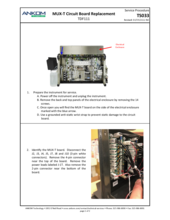
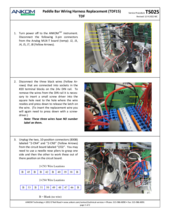
  1. If the wiring from the paddle bar to the circuit board is faulty, the E1 fault will occur for all six positions. If this happens, there are a couple possibilities.  First turn power off to the instrument and open the electrical enclosure.  Contact ANKOM Technology for more detailed instructions. Inspect the white 3-pin connector labeled “J2” that plugs into the circuit board labeled “MUX-T”.  This connector plugs in near the top of the MUX-T circuit board. Inspect the bottom of the three black wires in the J2 connector and be sure it is securely plugged into the connector.  If it is loose or has become disconnected this will cause an E1 fault at all six positions. If the crimp terminal on this wire is loose or has become disconnected this will also cause this fault.  If this wire appears to be securely connected into the 3-pin connector, also check to see if there is continuity from the from the same wire in the J2 connector to the other end of this wire in the 25-pin connector that the paddle bar cable plugs into.  You will have to disconnect the 25-pin paddle bar connector that plugs at the bottom of the electrical enclosure to confirm this with a voltmeter. If this is identified as the problem the TDF15 Paddle Bar Wire Harness will need to be replaced. Contact ANKOM Technology for further assistance.
  2. If the E1 fault is not related to all six positions then it is most likely related to the Temperature sensor within the paddle bar. When the run in progress is done, turn the instrument off and back on again.  Using the Diagnostics mode, select Temperatures and see if the station that reported the problem reading is still doing so.  If the problem reading is ongoing an E1 fault will display again.  If not, run a brief test.  Again using the Diagnostics mode, select Heater Test, press Paddle Heater Power Enable. Having done so, turn on all six paddle heaters. Monitor the temperatures closely to see if the E1 fault returns during heating of the paddles. Do not leave the instrument at this time as the heaters will stay on potentially overheating them if not controlled. Turn the heaters off when they reach 95˚C.  Allow the paddles to cool back to ambient temperature. If during the heating or cooling, the fault recurs, the Paddle Bar will need to be replaced. If the fault does not happen again, leave power on to the instrument overnight while in the Select a Function screen.  The program is always monitoring temperatures when power is on and if the fault occurs again during this time, the Paddle Bar will need to be replaced. If the fault does not recur during any of these tests, it is possible that a voltage fluctuation or static discharge near the sensor may have caused this fault.  The instrument may be put back into use. Keep record of any further E1 faults and if any do occur again, replace the Paddle Bar.
  3. It is also possible that the MUX-T circuit board is faulty.  This is the least likely of the possible problems.  Contact ANKOM Technology if the other options have been worked through and the problem persists.

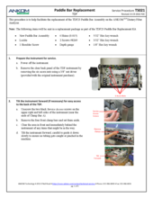
Refer to Service Procedure TS021 Paddle Bar Replacement for replacement of the Paddle Bar Assembly (TDF23).  This will require calibration of the temperature sensors and proper setting of the mixing stroke.  If the problem persists or any questions arise, contact ANKOM Technology for further assistance ([email protected] or 1-315-986-8090).

Documents for This Question

Procedure Title Download
21 Paddle Bar Replacement View PDF

I am getting an E2 Temperature Sensor Failure - Inline Heater fault during a run; what should I do?

To get this fault, the thermistor to the In-line Heater is reporting an erroneous low reading of < 10˚C.

The fault message on the Touch Screen Display will indicate that the In-line Heater is disabled.  The In-line Heater operates during IDF water rinses and 95% ethanol pre-heat when filling the SDF bags before the precipitation phase.  The run in progress will continue in spite of this fault.  If known, note the temperature of the In-Line Heater when this fault occurred. Depending on a number of factors the SDF results from this run may not be accurate.  Some samples may be more sensitive to lower temperature alcohol during the precipitation phase than others.  If this fault occurred late in the 95% alcohol pre-heat / delivery, the alcohol may have nearly reached the desired temperature. It may be advisable to repeat the run after the problem is corrected. If a temperature of 8˚C is seen for the in-line heater, this is likely a false reading and would indicate a disconnect in the Thermistor circuit. Turn the power off and open the electrical enclosure. Identify the “MUX-T” circuit board.  Locate the 3-pin connector labeled “J10” and be sure that this is securely connected to its location on the MUX-T board and that the red and white wires do not pull out of the connector easily.  If the J10 connector is loose, connect it securely and see if this resolves the problem.  If the problem continues the TDF98 TDF Thermistor Assembly within the In-Line Heater will need to be replaced.  If the problem persists, there may be an issue with the MUX-T board.

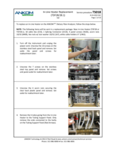
For replacement of the TDF98 TDF Thermistor Assembly see Service Procedure TS018 In-line Heater Replacement and refer to the steps specific to replacing the thermistor.

For further assistance, contact ANKOM Technology at [email protected] or 1-315-986-8090.

I am getting an E3 Paddle Heater Overtemp fault; what should I do?

To get this fault, the Temperature Sensor in one or more of the paddle heaters are reporting high temperatures. This could occur at different times under specific conditions.

  • During the Amylase phase or when the instrument is idle if a temperature of over 105°C is reported.
  • During the cooling cycle (after the Amylase phase) if after 20 minutes the bags have failed to drop in temperature to 62°C.
  • During the AMG or Protease phase if a temperature of over 70°C is reported.

Should any one of these conditions be met during a run, the run will be aborted. The E3 error message on the Touch Screen Display will indicate which station(s) are reporting the overtemp fault. This may be an actual overtemp condition or it may be erroneous due to a connectivity issue. Either way the heaters will be shut down by the program and the run is aborted. If this were to occur during an SDF precipitation, the heaters will be shut down, but the SDF precipitation will continue as normal.

To determine if the overtemp condition is real and the result of a heater that is failing to cycle or turn off, run the following test. Turn the power off to the instrument and allow the paddles to cool to room temperature. Now turn the power back on and from the Touch Screen Display, select Diagnostics. Press Temperatures to monitor the reported temperatures. At the same time, by touch, check the temperature of each paddle, especially the one that faulted earlier. If the suspect paddle begins getting warm, there is a problem with the paddle heater control. Turn the power off. This will require the replacement of the I/O-2 circuit board. Contact ANKOM Technology for further assistance ([email protected] or 1-315-986-8090).

If the previous test does not reveal a problem with the paddle(s) heating unregulated, take the following steps to identify the problem. Turn the TDF instrument power off and then back on.  From the Select a Function screen, press Diagnostics and select Temperatures. See if the suspect paddle heater is again reporting an abnormally high (false) reading while sitting at room temperature. If so, there is a fault in one of the temperature sensors and the Paddle Bar Assembly (TDF23) will need to be replaced. If the readings appear normal and the E3 fault does not recur, run a brief test. Again using the Diagnostics mode, select Heater Test, press Paddle Heater Power Enable. Having done so, turn on all six paddle heaters.  Monitor the temperatures closely to see if the E3 fault returns during heating of the paddles. Do not leave the instrument at this time as the heaters will stay on potentially overheating them if not controlled. Turn the heaters off when they reach 95°C.  Allow the paddles to cool back to ambient temperature. If during the heating or cooling, the fault recurs, the Paddle Bar will need to be replaced. If the fault does not happen again, leave power on to the instrument overnight while in the Select a Function screen.  The program is always monitoring temperatures when power is on and if the fault occurs again during this time, the Paddle Bar will need to be replaced. If the fault does not recur during any of these tests, it is possible that a voltage fluctuation or static discharge near the sensor may have caused this fault.  The instrument may be put back into use.  Keep record of any further E3 faults and if any do occur again, replace the Paddle Bar.

Refer to TDF Service Procedure #21 for replacement of the Paddle Bar Assembly (TDF23).  This will require calibration of the temperature sensors and proper setting of the mixing stroke.  If the problem persists or any questions arise, contact ANKOM Technology for further assistance ([email protected] or 1-315-986-8090.

I am getting an E4 In-Line Heater Overtemp fault; what should I do?

This fault occurs when the Temperature Sensor in the In-Line Heater reports a temperature exceeding 135˚C.   The E4 error message on the Touch Screen Display will indicate the temperature at the time of the fault. When this fault occurs the instrument automatically aborts the current run.
 
The In-Line Heater operates during IDF water rinses and when filling the SDF bags with 95% alcohol.  Possible causes for the E4 fault include:
 
1.        Empty chemical container during In-line heater operation (causing an actual overheat)
This fault can occur when water or alcohol containers are not filled adequately before the run and if they empty during the In-Line Heater operation. This may cause the In-Line Heater to exceed 135˚C in which case the heater will be disabled and the run aborted. If this happens one will likely see an E14 Empty Chemical Container fault as well.  If this has happened, the instrument is performing as intended to prevent uncontrolled heating of the In-Line Heater. Be sure to start a run with containers filled to the minimum level line.
 
2.        A short in the thermistor wiring (causing a false high reading) or a malfunctioning
           MUX-T circuit board (causing a false high reading)
A reading of 161˚C is reason to suspect a fault in the thermistor wiring. If this is the case, confirm that the In-line heater is not actually at this temperature. Turn the power off to the instrument and allow the In-Line Heater to cool to room temperature. Remove the clear back panel from the rear of the instrument. Turn the instrument back on and from the Select a Function screen press Diagnostics and then select Temperatures. Check to see that the In-Line Heater temperature sensor is reporting a temperature in line with the actual room temperature. If an IR thermometer is available this can be used to confirm that the In-line heater reading reflects its actual temperature.  Be cautious when doing so as it could be getting very hot if there is a problem with the heater control. If the In-Line Heater is physically cool while a high temperature is reported on the display, then there is a problem with either the thermistor (temperature sensor) or MUX-T circuit board. Turn power off to the instrument.
 
3.        Malfunctioning Heater Relay or I/O-2 Circuit board (causing an actual overheat)
If the In-Line Heater is actually heating – and this is confirmed both by sensing the heat coming off the heater and by a steady rise in temperature on the In-Line Heater Temperatures display – turn power off and unplug the instrument. In this case there would be a problem with either the Heater Relay or the I/O-2 Circuit board.
 
For replacement parts and further assistance, contact ANKOM Technology at [email protected] or 1-315-986-8090.  For replacement of an in-line heater, click the In-Line Heater Replacement service procedure link shown below.

I am getting an E5 Paddle Heater Under Temp fault during a run; what should I do?

To get this fault, the temperature sensor in one or more of the paddle heaters is reporting low temperatures. This could occur at different times under specific conditions.

  • During paddle pre-heat if any one of the paddles do not reach 50°C in 5 minutes.
  • During the Amylase phase if any one of the paddle sensors does not reach 90°C in 25 minutes.  Also applies to Trizma phase in the AOAC2009.01/2011.25 methods.
  • During the AMG or Protease phase if any of the paddle sensors fail to maintain at least 45°C (temperature range is 60°C +10/-15°C). Also applies to Protease phase during AOAC2009.01/2011.25 methods.

Should any one of these conditions be met during a run, the suspect heater/station will be shut down and stop heating.  The run will otherwise continue as normal. The E5 error message on the Touch Screen Display will indicate which station(s) are reporting the undertemp fault and what the temperature was at the time of the fault. This may be an actual undertemp condition or it may be erroneous due to a connectivity issue.  Either way the affected heater will be shut down by the program and the run will continue. If this were to occur during the IDF phase, with the heater being shut down, digestion will likely not occur as normal and the test results will not be reliable for this station.

Below is a list of potential causes of the E5 fault:

  1. Bag breakage: Confirm that an IDF or Flow-thru bag did not break during one of the heating periods. If a bag were to leak near Clamp Bar B and if fluids were to get on one of the paddles, the liquid evaporation will drop the paddle temperature and possibly cause this fault.  If this has occurred, the instrument is sensing a real drop in temperature at the wetted paddle and no repair to the instrument is needed. Clean the area from the leaked bag. Test results from a broken bag should be disregarded.
  2. Greater volume in the IDF or Flow-thru bags: Confirm that the volume calibration is accurate. Rerun the volume calibration as described in the operator's manual (QC/Calibration Checks section). If, for example, the volume calibration is significantly off, there could be an average of 50mls of buffer delivered instead of the required 40mls. This would create a delay in reaching temperature.
  3. Pre-heat of paddles has been by-passed: In Diagnostics there is the option under Service Mode to "Bypass Amylase Phase Initial Heat-up." If this has been inadvertently pressed (stating "YES") this will bypass the paddle preheat to 50°C and take longer to heat up once the Buffer/Amylase is added. Make sure this option says "NO." This feature is typically used only for demo purposes.
  4. Clamp Bar A is left open: If for any reason Clamp Bar A was left open during the Amylase phase heat up, there will be more evaporative cooling which will require more time ro heat the bags. NOTE: normally Clamp Bar A will close automatically after the final delivery to the IDF positions, but it can be re-opened.
  5. Front cover left open or localized draft: Be sure to use the front safety cover, especially during the Amylase phase. If this cover is left open, and/or if there is a nearby A/C vent creating a draft toward the front of the instrument the Amylase phase heat-up will take longer. Also, if the TDF instrument is located inside a hood, turn off the air flow to the hood during the Amylase phase heat-up. The continued upward airflow will create a significant delay in reaching temperature. Addressing these may resolve the problem.
  6. Alcohol - Buffer containers connected incorrectly: Ensure that the containers are connected correctly to the color-coded supply lines on the right side of the instrument. Confirm that alcohol did not inadvertently get put in the buffer container, and that buffer was not put in the alcohol containers. If either of these things happen, and alcohol gets dispensed to the IDF bags at the start of the Amylase phase, the alcohol will boil at a much lower temperature and not reach the target temperature of 97°C.

If the E5 fault was not the result of one of the above issues, run a brief test to see if all the paddle heaters are heating normally. Allow the paddles to return to room temperature. Obtain a stopwatch and 6 Flow-thru bags (used bags will work for this test). Use a heat sealer to seal the bottom edge of the bags. This will make removal later easier. Install these in the IDF positions. Connect the TDF70 Flush Tubing assembly to the HCL, 3 enzymes, buffer, water, and 2 alcohol connection points on either side of the instrument. Connect the middle connector to a filled Distilled Water container. From the Select a Function screen select a 991.43 TDF run. Answer all the prompts affirmative and press START. Press the "Display Temps/Pressures" button to monitor the temperature readings and watch the time that they reach 50°C. They should reach this temperature in about 2 to 2.5 minutes depending on the ambient starting temperature. Note the amount of time required. Reset your timer. As soon as Amylase and Buffer are delivered, mixing will start and restart your timer. Use the chart below to record every 2.5 minutes, the time it takes for each paddle to reach 90°C. T0 is the end of the fluid delivery to the bags and start of mixing. Once they all reach 90°C, press ABORT to end the run and allow the bags to cool before removal.

Turn heaters off immediately after this test. If the suspect paddle heater takes significantly longer to heat than the others or fails to heat up, there is a problem with either the heater within the Paddle Bar Assembly or with the I/O2 circuit board. If the Paddles heat to the touch but one of the sensors shows an erroneous low reading, there is a problem with the sensor, and the Paddle Bar assembly will need to be replaced.  For further assistance, contact ANKOM Technology at [email protected] or 1-315-986-8090. Follow TDF Service Procedure #TS021 for replacement instructions of the Paddle Bar assembly (TDF23).
If one of the paddles fails to heat normally, and to rule out a problem with the I/O2 circuit board, remove the back and top panel of the Electrical Enclosure so that the I/O2 circuit board can be seen. Do not touch wiring. Individually turn on the paddle heaters one at a time checking to see that the appropriate LED light on the I/O2 circuit board lights up when the paddle is supposed to be heating. The following is a list of the Paddles and the corresponding LED #:
  • Paddle Heater Power Enable - LED 2
  • Paddle 1 - LED 15
  • Paddle 2 - LED 12
  • Paddle 3 - LED 9
  • Paddle 4 - LED 7
  • Paddle 5 - LED 4
  • Paddle 6 - LED 1

Turn heaters off after each test. If the appropriate LED is not lighting up, the problem may be with either the power supply or the I/O2 circuit board.  To test the power coming from the power supply to the individual paddle heater use a voltmeter set to DC. Connect the red lead on the voltmeter to the #20 position on the 24 volt DIN rail.  Now turn all the heaters on and test voltage as follows. On the back of the I/O2 circuit board are two 10-pin connectors labeled CN-3 and CN-4.  To test the power to each paddle, touch the black lead of the voltmeter to the following contact. 

  • Paddle 1 - CN4, #2 position (wire label 53)
  • Paddle 2 - CN4, #5 position (wire label 50)
  • Paddle 3 - CN4, #8 position (wire label 47)
  • Paddle 4 - CN3, #2 position (wire label 45)
  • Paddle 5 - CN3, #5 position (wire label 42)
  • Paddle 6 - CN3, #8 position (wire label 39)

You should detect 25.0 volts +/- 0.2 volts at each circuit.  If voltage is low there may a problem with the power supply or voltage adjustment.   For further assistance, contact ANKOM Technology at [email protected] or 1-315-986-8090. 

If all the LEDs are lighting up as normal and voltage is normal, the problem is with a paddle heater within the Paddle Bar Assembly.  For further assistance, contact ANKOM Technology at [email protected] or 1-315-986-8090.  Follow Service Procedure #TS021 for replacement instructions of the Paddle Bar assembly (TDF23).

I am getting an E7 In-Line Heater Under Temp alert during a run; what should I do?

This fault occurs when the Temperature Sensor in the In-Line Heater reports that the In-Line Heater is not reaching the required 110˚C within the 90 seconds allotted during an IDF water rinse.  The fault message on the Touch Screen Display will indicate that the In-line Heater is disabled.  The operator will be able to select OK and continue the run, but the cause should be investigated later.
 
The In-line Heater operates during IDF water rinses to facilitate rinsing of the IDF bag and to ensure that solutions when deposited into the SDF bag are nominally the same temperature as the pre-heated alcohol.  The run in progress will continue in spite of this fault.  If known, note the temperature of the In-Line Heater when this fault occurred.
 
Typically the test results from this run would not be affected by the cooler water rinse temperatures. Be sure that the sample in the IDF bag was rinsed down into the filter area of the bag and observe the precipitation phase for SDF.  If any anomalies are noted pay particular attention to the test results as it is possible results for certain sample types may be more sensitive to lower temperature during the precipitation phase than others.  It may be advisable to repeat the run after the problem is corrected. 
 
After the assay with the fault is complete, turn the power off to the instrument and turn it back on to clear the fault. Test the In-line heater under Diagnostics / Heater Test.  With a timer handy, observe how quickly the in-line heater heats up. Start the timer and immediately turn the In-line heater on and watch for it to get up to 70˚C.  It should reach 70˚C in 40-45 seconds. Turn it off as soon as 70˚C is reached. Confirm with an IR thermometer that the temperature reading on the touch screen display matches the actual temperature of the In-line heater based on the reading taken with the IR thermometer.  The two readings should be ± 5˚C of each other.   
 
If the In-line heater temperature appears to be frozen at 8˚C, there is likely a problem with a disconnected Thermistor wire at the MUX-T board or a lack of continuity in the Thermistor wiring.
 
If this fault is the result of a false low temperature reading, or if you need any further assistance, contact ANKOM Technology at [email protected] or 1-315-986-8090.
 
For replacement of an in-line heater, click the In-Line Heater Replacement service procedure link shown below.

I am getting an E8 In-Line Heater Under Temp alert during a run; what should I do?

This fault occurs when the Temperature Sensor to the In-Line Heater reports that the In-Line Heater is not reaching the required 80˚C within the 90 seconds allotted during an EtOH95 delivery.  The fault message on the Touch Screen Display will indicate that the In-line Heater is disabled.  The operator will be able to select OK and continue the run, but the cause should be investigated later.
 
The In-line Heater operates during the EtOH95 delivery to the SDF bags.  The run in progress will continue in spite of this fault.  If known, note the temperature of the In-Line Heater when this fault occurred. Typically the test results from this run would not be affected by the cooler ethanol temperatures. Observe the precipitation phase for SDF.  If any anomalies are noted pay particular attention to the test results as it is possible results for certain sample types may be more sensitive to lower temperature during the precipitation phase than others.  It may be advisable to repeat the run after the problem is corrected. 
 
After the assay with the fault is complete, turn the power off to the instrument and turn it back on to clear the fault. Test the In-line heater under Diagnostics / Heater Test.  With a timer handy, observe how quickly the in-line heater heats up. Start the timer and immediately turn the In-line heater on and watch for it to get up to 70˚C.  It should reach 70˚C in 40-45 seconds. Turn it off as soon as 70˚C is reached. Confirm with an IR thermometer that the temperature reading on the touch screen display matches the actual temperature of the In-line heater based on the reading taken with the IR thermometer.  The two readings should be ± 5˚C of each other.
 
If the In-line heater temperature appears to be frozen at 8˚C, there is likely a problem with a disconnected Thermistor wire at the MUX-T board or a lack of continuity in the Thermistor wiring.
 
If this fault is the result of a false low temperature reading, or if you need any further assistance, contact ANKOM Technology at [email protected] or 1-315-986-8090.
 
For replacement of an in-line heater, click the In-Line Heater Replacement service procedure link shown below.

I am getting an E9 In-Line Heater Overtemp alert or fault; what should I do?

This fault occurs when the Temperature Sensor reports a high temperature while the In-Line Heater is attempting to cool within the required timeframe.  Cooling is facilitated by flushing water through the lines of the In-line heater.  
 
The first time this occurs during a run, the operator will have the option to “CONTINUE” or “ABORT”.  If “CONTINUE” is selected the pump will resume flushing water through the in-line heater to bring the temperature down. If high temperature is reported again, the run will be aborted and an E9 In-line Heater Overtemp Fault will be displayed.  
 
Possible causes for the E9 fault include:
 
1.        Empty chemical container during In-line heater cool down cycle (causing a cool-down failure)
The In-Line Heater is being cooled after the IDF water rinses and after the 95% alcohol delivery to the SDF bags.  If the In-Line Heater fails to cool in the required amount of time, this fault can occur.  It could be the result of an empty water container. If this happens one will likely see an E14 Empty Chemical Container fault as well.  If this has happened, the instrument is performing as intended to prevent uncontrolled heating of the In-Line Heater. Be sure to start a run with containers filled to the minimum level line.
 
2.        A short in the thermistor wiring or a malfunctioning MUX-T circuit board
A reading of 161˚C is reason to suspect a fault in the thermistor wiring. If this is the case, confirm that the In-line heater is not actually at this temperature. Turn the power off to the instrument and allow the In-Line Heater to cool to room temperature. Remove the clear back panel from the rear of the instrument. Turn the instrument back on and from the Select a Function screen press Diagnostics and then select Temperatures. Check to see that the In-Line Heater temperature sensor is reporting a temperature in line with the actual room temperature. If an IR thermometer is available this can be used to confirm that the In-line heater reading reflects its actual temperature.  Be cautious when doing so as it could be getting very hot if there is a problem with the heater control. If the In-Line Heater is physically cool while a high temperature is reported on the display, then there is a problem with either the thermistor (temperature sensor) or MUX-T circuit board. Turn power off to the instrument.
 
3.        Malfunctioning Heater Relay or I/O-2 Circuit board
If the In-Line Heater is actually heating – and this is confirmed both by sensing the heat coming off the heater and by a steady rise in temperature on the In-Line Heater Temperatures display – turn power off and unplug the instrument. In this case there would be a problem with either the Heater Relay or the I/O-2 Circuit board.
 
For replacement parts and further assistance, contact ANKOM Technology at [email protected] or 1-315-986-8090.  For replacement of an in-line heater, click the In-Line Heater Replacement service procedure link shown below.

I am getting an E10 High Line Pressure fault during a run; what should I do?

An E10 fault is the result of one or more of the six pressure sensors reading a pressure above 20 psi during the initial buffer delivery at the beginning of the IDF phase or during the EtOH95 delivery to the SDF bags.  This fault will abort the run.  The fault screen will identify which line or lines are showing the high pressure.
 
The three main reasons for this fault are:
 
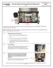
1.        An input valve (SDF or IDF) is failing to open, or pinch tubing is stuck closed.
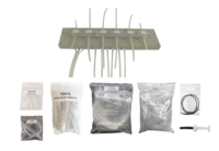
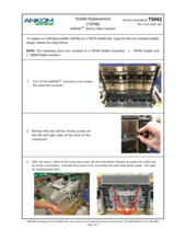
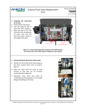
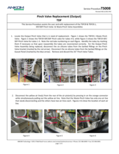
Check the fault screen to identify which line, or lines, are showing the high pressure and note this along with any pressure readings.  If the fault was appearing on three lines at the same time, such as SDF lines 4,5 and 6; or IDF lines 1, 2 and 3, for example, this would indicate a blockage at one of the IDF or SDF inlet valves.  The pinch tubing within the IDF or SDF inlet valves may be stuck closed, or the valve may be failing to open. Remove the hitch pin from the pinch bar at the suspect valve and slide the pinch bar out. Using “Diagnostics” / “Valve Test” toggle the IDF Inlet or SDF Inlet valve and see if the valve is actuating properly.  If the valve is not actuating properly the valve will need to be replaced. This can be ordered as part TDF29 Pinch valve - IDF,SDF Assembly.  Installation instructions can be found in Service Procedure TS008 (see link below). While you have the valve open look at the pinch tubing to determine if it is stuck closed.  Pinch valve tubing should be replaced on an annual basis. If this has not been done and if the tubing is flattened and appears stuck closed, replace all of the 21 tube sections within the IDF, SDF, Waste and Enzyme pinch valves. A spare set of tubes comes with the instrument on original purchase, and more can be ordered as part TDF71 Pinch Valve Tubing Set.  Installation instructions can be found in Service Procedure TS005 (see link below).
 
2.        There could be a blockage in one of the tubes or fill nozzles.
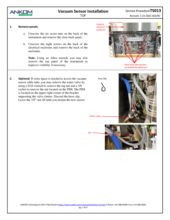
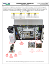
Look for a blockage in the fluid lines between the pressure sensor assembly and the fill nozzle. This can be a problem if the fluid lines have not been flushed regularly with ethanol as recommended in the Operator’s Manual. Mold growth can occur in the buffer, water or enzyme lines; and dried enzyme can become lodged in some of the smaller orifices.  If mold growth is observed this will need to be addressed with tubing replacement and weekly flushing of the lines with alcohol.  For tubing replacement review Service Procedure TS006 (for delivery tubing - see link below) or Service Procedure TS007 (for supply tubing - see link below). To confirm a blockage, run a Motor Test. Make sure the water container is plugged into its fitting and select “Diagnostics” and then “Motor Test”.  Press “Set Valves” and open only the Water Supply and close all other supply valves. Open the IDF or SDF Inlet valve (depending on whether the blockage was found at the IDF or SDF position).  Close the other Inlet valve and the Waste valve.  Place six, 100ml beakers under the IDF or SDF fill nozzles. Press the back button (←) to return to the Motor Test screen. Select a volume of 20 mls, and press “GO”.  See if the line(s) that had the E10 high line pressure fault deliver approximately 20 mls or a noticeably lesser volume of fluid. If less or no fluid is delivered from the suspect line the result has been confirmed and the blockage will need to be cleared. First inspect the spray tip at the end of the fill nozzle. Each spray tip has six, 0.020” (0.5mm) holes in it that may have become blocked. Remove the spray tip, inspect the holes with the TDF45 Illuminated Magnifier and clean with the TDF94 Spray Tip cleaning tool. Also trace the fluid line from the pressure sensor bracket to the fill nozzle, disconnecting fittings and looking for any blockage. Tubing replacement service procedures are noted above, if needed.  Spare (delivery) silicone tubing can be ordered as part TDF77, and spare (supply) tubing can be ordered as part TDF78.
 
3.        One of the pressure sensors could be faulty.
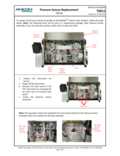
If the cause of the fault has still not been identified, turn the machine off and back on again. Select “Diagnostics” and press “Pressures”.  At this point the IDF, SDF and Waste valves should all be open and the pressure sensors should all be reading atmospheric pressure.  Note what the pressure readings are for all of the lines.  Atmospheric pressure will vary depending on elevation and weather patterns, but for an instrument at sea level, the pressure should be approximately 14.5 psi. Variation of +/- 0.3 psi from sensor to sensor is normal and will not affect results as the instrument is looking at pressure differentials at different points during the run.  The E10 fault will only appear if the differential is 20 psi above the baseline atmospheric reading. If one of the lines is showing an errant pressure reading outside a range of +/- 0.3 psi from the average reading, the pressure sensor assembly should be replaced.  An errant reading at ambient pressure could indicate a skewed pressure differential reading during a fluid delivery.  If there is a problem with the pressure sensor ambient reading, the Pressure Sensor Assembly will need to be replaced. The Pressure Sensor Assembly can be ordered as part TDF19.  Refer to Service Procedure TS011 (see link below) for installation instructions.
 
For further assistance, contact ANKOM Technology at service @ankom.com or call 1-315-986-8090. 

Documents for This Question

Procedure Title Download
08 Pinch Valve Replacement (Output) View PDF
07 Tube Replacement (Supply Line) View PDF

I am getting an E11 Low Input Pressure fault during a run; what do I do?

An E11 fault is the result of the high pressure sensor reading input pressure below 35 psi.  N2 Input pressure is always being monitored and the fault could occur at any point during a run. The fault will interrupt the run and wait for the operator to correct the problem. This problem can result from one of the following causes:

1)    The nitrogen tank has run low.
Most often this problem is because the nitrogen tank has run low and needs to be replaced, or because a valve was closed that supplied the instrument.  This could also be because the regulator was inadvertently adjusted too low and needs to be reset, up to the correct input pressure (50-55 psi gauge pressure).  Check the tank pressure and replace it if needed. Confirm that the regulator is set to 50-55 psi.  If the problem is corrected you can resume a run in progress.
2)    There is a substantial leak in one of the high pressure nitrogen lines.
If there is a substantial leak in one of the high pressure nitrogen lines, this would also cause an E11 fault. The loss of air from a leak would be audible and should be easily identified. Turn the instrument off and close the nitrogen lines. Replacement tubing, if needed, can be ordered as part 8216 Black Nitrogen Supply Tubing.  It is sold per foot and can be cut to length.
3)    The regulator is not working correctly.
It is possible that the regulator is not working correctly.  Check the regulator setting and compare it with the reading from the Pressures screen under Diagnostics.  The Diagnostics / Pressures screen displays in absolute pressure which includes atmospheric + gauge pressure.  Therefore if the gauge pressure reads 50 psi and atmospheric pressure is 14.5 psi, the pressure displayed in the Diagnostics / Pressures screen will be 64.5 psi.  Confirm that the gauge pressure correlates with the Diagnostics/Pressures reading.  If the regulator is not adjusting pressure correctly it will not deliver the correct pressure.  In this is the case you will need to replace part TDF61 Pressure Regulator 60 psi.
4)    The High Pressure Sensor circuit has become shorted.
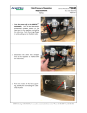
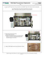
It is possible that the High Pressure Sensor circuit has become shorted. If the black and white wires on the TDF16 High Pressure Sensor have been shorted, a false low reading will result.  If you confirm that the correct pressure is getting to the lines and the regulator is working correctly, then the pressure sensor will need to be replaced.  Refer to Service Procedure TS002 for replacement of the TDF16 High Pressure Sensor Assembly.
 
For further assistance, contact ANKOM Technology at [email protected] or call 1-315-986-8090.
 

Documents for This Question

Procedure Title Download
02 High Pressure Sensor Replacement View PDF

I am getting an E12 High N2 Input Pressure fault during a run; what should I do?

An E12 fault is the result of the high pressure sensors reading input pressure above 100 psi.  N2 Input pressure is always being monitored and the fault could occur at any point during a run. The fault will interrupt the run and wait for the operator to correct the problem. This problem can result from one of the following causes:

1)    The regulator was inadvertently adjusted too high.
Typically the problem is a result of the regulator inadvertently being adjusted too high. Check the regulator and reset it to 50-55 psi if needed. If the problem is corrected, you can resume a run that is in progress.

2)    The dial on the regulator is broken.
Check the regulator setting and compare it with the reading from the Pressures screen under Diagnostics.  The Diagnostics / Pressures screen displays in absolute pressure which includes atmospheric + gauge pressure.  Therefore if the gauge pressure reads 50 psi and atmospheric pressure is 14.5 psi, the pressure displayed in the Diagnostics / Pressures screen will be 64.5 psi.  Confirm that this is the case.  If the gauge is broken and is reading low and if the regulator has been adjusted high it could possibly have been adjusted beyond 100 psi causing this fault.  If this is the case you will need to replace part TDF61 Pressure Regulator 60 psi.

3)    The High Pressure Sensor has become disconnected.
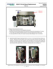
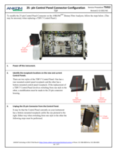
To determine if this is the case you will need to open up the electrical enclosure.  First, turn power off to the instrument. Then remove the back and top panels to the electrical enclosure.  Clear the bench in front of the instrument and remove the four front clamp bars and set them aside. Tilt the instrument forward.  From the front of the instrument view the right side of the electrical enclosure. There are two, 5 cm x 10 cm circuit boards, one of which is labeled “MUX-P”. On this circuit board is a white connector that is labeled “J10”. Make sure this is plugged in.  If it is loose or has become dislodged from the three pins below the J9 connector this would cause a false high pressure reading and an E12 fault. Also make sure the red, black and white wires are secure within the white J10 connector. If a secure connection is restored, retest the pressure. Staying clear of the open electrical enclosure, turn the power back on to the instrument and recheck the input pressure reading. If this is now in the typical 60-70 psi range, the problem is resolved.  Turn power off to the instrument and close the electrical enclosure.

4)    The High Pressure Sensor is not working.
If the all the above possibilities have been explored and the problem persists, replace the TDF16 High Pressure Sensor using Service Procedure TS002.
 
For further assistance, contact ANKOM Technology at [email protected] or call 1-315-986-8090.

Documents for This Question

Procedure Title Download
02 High Pressure Sensor Replacement View PDF

I am getting an E13 Pump Tube Failure fault during a run; what do I do?

Refer to TDF Service Procedure #1, to diagnose a tubing pressure failure.

Documents for This Question

Procedure Title Download
01 Fault Analysis (E13 - Tubing Pressure Failure) View PDF

I am getting an E14 Empty Chemical Container fault during a run; what should I do?

The Touch Screen Display will give you the option to Retry, Override, or Abort the run.  Retry will simply try the delivery again; Override will ignore the fault for the remainder of the run; and Abort will stop the run entirely.

The most likely cause of an E14 fault is an empty chemical container.  The fault screen will identify the container that was being drawn from when the error occurred.  The vacuum sensor is designed to monitor vacuum pressure on the supply lines when they are being drawn from.  When there is little or no vacuum on the line, this fault presents.  Refill the appropriate container as needed and select “Retry”.

Another potential cause of an E14 fault is a leak in any one of the supply tubes or fittings that would allow air to get pulled into a supply line. To test for this, under “Diagnostics”, run a “Motor Test and first “Set Valves”.  Open the supply line valve that generated the fault and open the Waste valve.  Set the volume to 40 mls and press “GO”.  Observe the supply lines at the rear of the instrument or tilt the instrument forward using the pivot mechanism to see the supply lines. Look for any air being drawn in at a hole in the tubing or at a crack in a fitting.  If this is observed, tubing or fittings may need to be replaced.  For further assistance contact ANKOM Technology at [email protected] or 1-315-986-8090.

Another possible cause of an E14 fault is an interruption in the Pump Motor Controller (PMC) operation.  If the PMC hesitates or stops because it has overheated or because the electronics on the circuit board have been compromised, the pause in operation will cause a drop in vacuum pressure and trigger an E14 fault.   This is possible even if the pause in operation were only for a second or two.  You should be able to retry and continue without a problem if that is the case; however, perform further testing after the run is complete.  After the run, perform a “Motor Test” under “Diagnostics” after first setting valves to Water Supply open and Waste open with all other valves closed. Set the volume to    250 mls – this will simulate the length in time of operation for a 95% alcohol delivery. Fill and plug in the water container. Press “GO” and listen for the Pump Motor operation.  Be attentive to any pause in the pump’s operation. The pump should run continuously for 6.5 – 8.5 minutes, depending on the volume calibration setting for your specific instrument. Stay with the instrument for the entire delivery.  Refill the water container when it nears empty, as it will draw more than 1 liter of water (250mls x 6).    If no pause in operation is noticed, allow the instrument to sit idle for 10 minutes and repeat the test.  If a hesitation or pause in operation is witnessed during the lengthy pump operation time the Pump Motor Controller will need to be replaced.  For further assistance contact ANKOM Technology at [email protected] or 1-315-986-8090.

I am getting an E15 Supply Line Plugged fault during a run; what should I do?

The Touch Screen Display will give you the option to retry, override, or abort the run. 
  • Retry will simply try the delivery again.
  • Override will ignore the fault for the remainder of the run.
  • Abort will stop the run entirely.
 
To analyze the problem, do the following:
When the instrument is not in the process of running an analysis, an E15 fault can be investigated by performing a Motor Test under Diagnostics.  From the Motor Test screen, press Set Valves and select the valve that caused the fault.  If this is not known, test each supply valve. Open only one supply valve at a time and close all others.  Open the Waste output valve and close the IDF and SDF output valves.  Be sure that there is adequate fluid in the reservoir that is being tested. Change the delivery volume to 20 ml and press GO.  Watch the vacuum reading on the screen.  Typical readings are between 0.7 – 1.5 psi.  A reading above 3 psi will generate an E15 fault (during a run).  If one of the supply lines shows a high reading, you have isolated the supply line that is causing the problem.
              
Possible causes of an E15 fault include:
1)  Clogged Filter
The most likely cause of an E15 fault at the Water, Buffer, EtOH78, EtOH95 or HCl lines is a clogged filter. Severely clogged filters may reduce delivery volumes and affect results. The filters are at the end of the draw tubes inside of the containers.  These should be checked and cleaned on a monthly basis and cleaned as needed. The filters can usually be cleaned with a soft bristle brush under running water. If they can't be cleaned, there are two spares of the plastic type container filters (used for water, alcohols and HCl/Acetic Acid) and one spare of the metal screen filters (used for buffer) included with the instrument on original purchase. Additional ones may be ordered as part 8202 (plastic filter) and part 8203 (metal screen filter).    
 
2)  Quick Disconnect Fitting not fully locked in place
A quick disconnect fitting functions as a valve that closes when disconnected or not fully connected. Quick disconnect fittings are found at the following reservoirs: enzymes, water, buffer, and alcohols.  Check to make sure that they cannot be pulled out without pressing the release button. If they can be pulled out without use of the release button they are not fully engaged and fluids will not be drawn. Push them into the adjoining fitting until you hear them snap in place. Confirm that they cannot be pulled out. It is also possible that the fittings may need to be replaced – see part 8193 (coupling body) and 8194 (coupling insert) on the ANKOM website.
 
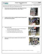
3)  Worn tubing in the Enzyme Pinch Valve
An E15 fault at one of the Enzyme lines (Amylase, Protease, or AMG) could be due to worn tubing in the Enzyme Pinch Valve. As the tubing in the Enzyme Pinch Valve ages it may become stuck closed preventing the flow of enzymes. Review and follow Service Procedure #004, first replacing the tubing within the pinch valve.  These tubes should be replaced annually. Spare pinch valve tubing comes with the TDF instrument upon original purchase; additional ones can be ordered as part TDF71 Pinch Valve Tubing Set (21 pcs). Also inspect the supply lines to see if there is a clog or pinch in the line. These also may require replacement.  A set of all enzyme tubes can be ordered as part TDF67 Enzyme Tubing Replacement Kit.  If the problem persists, contact ANKOM Technology at [email protected] or 1-315-986-8090 for further assistance.
 
4)  Pinched or plugged supply line or a faulty supply valve
Other possible causes for an E15 fault are a pinched or plugged supply line or a faulty supply valve.  Inspect the supply line in question to see if such a problem can be seen visually.  After having cleaned and/or replaced the filter and having checked for fully engaged disconnect fittings, if the problem persists, contact ANKOM Technology at [email protected] or 1-315-986-8090 for further assistance.

Documents for This Question

Procedure Title Download
04 Tube Replacement (Enzymes) View PDF

My enzymes do not appear to be pumping (the volume in the reservoirs is staying the same); what should I do?

The enzyme tubing may be clogged. Look at the enzyme tubing from the reservoirs to the Enzyme Pinch Valve and beyond to the Manifold. If there is any discoloration or gelled material in the tubing, replace the tubing.

Email ANKOM Technology at [email protected] or call 315-986-8090 to purchase your Enzyme Tubing Replacement Kit (TDF67).

Refer to TDF Service Procedure #4 for installation instructions.

Documents for This Question

Procedure Title Download
04 Tube Replacement (Enzymes) View PDF

Why is an incorrect volume of enzyme and/or an incorrect type of enzyme being drawn after new silicone tubing is installed at the enzyme pinch valve?

Refer to TDF Service Procedure #4 and reference the steps related to relaxing or pre-stressing the replacement Silicone Tubing by rolling them with a rod or dowel.

Documents for This Question

Procedure Title Download
04 Tube Replacement (Enzymes) View PDF

Why do the enzyme tubes appear discolored (yellow or brownish) or gelled?

This may occur if enzymes are used without a preservative. ANKOM recommends the use of a small concentration of Sodium Azide in the enzymes to prevent them from supporting bacterial, fungal or mold growth.Refer to the IDF/SDF Analysis section of the TDF Operator's Manual for more details.If enzyme tubes have become discolored, turned yellow or brownish, or if the enzyme has begun to gel in the tubes, they will require replacement.Refer to TDF Service Procedure #4 for instructions on doing this.Contact ANKOM Technology at [email protected] or call 315-986-8090 to purchase your Enzyme Tubing Replacement Kit (TDF67).

Documents for This Question

Procedure Title Download
04 Tube Replacement (Enzymes) View PDF

Why am I seeing different fluid levels in the filter bags at stations 1-3 vs. 4-6?

This may be the result of one of the IDF or SDF valves being stuck in a closed or partially closed position. Using the Diagnositcs screen select "Valve Test" and look for "IDF Inlet", "SDF Inlet" and "Waste" buttons. Run a brief test using the screen to open and close each valve. Confirm by looking at the pinch valve at the back of the instrument to see that it is opening and closing properly. If any of the valves are not opening properly, refer to TDF Service Procedure #8 to replace the pinch valve. The TDF29 Pinch Valve Assembly-IDF/SDF or TDF29.1 Pinch Valve Assembly- Waste can be ordered through the Product Catalog on this website or by calling 315-986-8090.

Documents for This Question

Procedure Title Download
08 Pinch Valve Replacement (Output) View PDF

Little or no fluid is being delivered to the IDF and/or SDF spray nozzles at one bag position; what should I do?

This problem could point to one of four possible issues with the instrument.

1) There could be a hole in that bag position’s fluid line after or within the PUMP causing a leak in the back of the instrument.  To determine of this is a problem, tilt the instrument forward and look for a leak from the silicone tubing. Open the PUMP doors and check for leaks from the Pump Tubes. Use Diagnostics to run a Pump Tube Test and check for leaks in the post-pump tubing specific to the problematic line.  Observe the pressure result from the line in question.  If there is a leak, a fitting or tube may need to be replaced. Contact ANKOM Technology at [email protected] or 1-315-986-8090 for replacement parts. If there are no leaks but the pressure result for the suspect line is low from the Pump Tube Test, this would point to a leak prior to the pump causing the pump to suck air through the hole OR a blockage in the line somewhere along the suspect tube length.

2) There could be a leak in the fluid line prior to the PUMP. To determine if there is a leak in the tubing line prior to the pump, run the following test. Under Diagnostics, run a Motor Test.  Set valves such that Waste is the only Output valve open and close all the Input valves.  Set the Motor Direction to REV (reverse). Put the ends of the Waste tubes in a beaker of water but before pulling them off of the tubing holder label them individually 1-6 for easy identification and re-attachment later. Leave the volume set to 10 mls and press GO.  Look for any leaks prior to the pump. Follow the suspect tube back from the PUMP to the MANIFOLD looking for any leaks along the suspect line.  If there is a leak, a fitting, tube, or MANIFOLD may need to be replaced.  Contact ANKOM Technology at [email protected] or 1-315-986-8090 for replacement parts. If there is no leak before or after the pump, proceed to issue #3 below.

3) There could be a blockage in a fluid line prior to the PUMP. To identify a blockage in a line prior to the PUMP, run the following test.  Under Diagnostics, run a Motor Test.  Set valves such that Waste is the only Output valve open and close all the Input valves.  Set the Motor Direction to REV (reverse). Put the ends of the Waste tubes in a beaker of water but before pulling them off of the tubing holder label them individually 1-6 for easy identification and re-attachment later. Disconnect the single (larger diameter tube) at the bottom of the MANIFOLD from the 6-way fitting. Leave the short (1 ½”) length of tube attached to the bottom of the MANIFOLD.  Leave the volume set to 10 mls and press GO.  Collect the fluid from the bottom of the MANIFOLD into a clean beaker.  Look for any particles, dried enzyme, or mold growth being washed out.  If contaminants are seen, repeat this but draw Ethanol in at the Waste lines and repeat until the collected fluid is clear.

4) There could be a blockage in a fluid line after the PUMP. To identify a blockage in a line after the pump, consider the following.  First it should be noted that by performing the procedure in #3 above, a blockage may have been flushed backward through the line and out through the MANIFOLD. In most cases performing the procedure in #3 will correct a blockage before or after the pump, but if it does not, contact ANKOM Technology at [email protected] or 1-315-986-8090 for additional diagnosing direction.
 
After identifying and resolving the problem, reconnect all tubing and repeat a Pump Tube Test to be sure each tube is being pressurized and holding pressure properly. Also run a Motor Test setting the Supply valve WATER to open and the IDF Output to open. Make sure the Motor Direction is FWD (forward) and place six beakers under the IDF delivery nozzles. Press GO and confirm fluid is delivered to each beaker equally.  Do the same with the SDF Output valve open and beakers under the SDF delivery nozzles.  If these tests pass, your instrument is ready to be put back into service.  

Filtration is slow at one of the stations on my TDF instrument. How can this be corrected?

Some variability in filter times is normal.  Default filter time settings take into account much of this variability.  Default settings for IDF/SDF filtration are as follows: IDF after release of bar B (5.0 min), IDF after water rinses (1.0 min), IDF after EtOH rinses (1.0 min), SDF after release of bar D (10.0 min), SDF after EtOH rinses 3.0 min).  The following are several factors that may contribute to slow filtration (taking longer than the default settings).

Lower air pressure
Make sure that the low pressure regulator is set properly.  Our recommended setting for the low pressure regulator is 4.0 PSI (static).  Do not adjust the regulator during filtration.  If your regulator is set lower than this, adjust the regulator and run the instrument again.  It should also be noted that during filtration, time may be added if slow filtration is observed.  As filtration is occurring a button will appear on screen that states, "Filter Time +".  Each time this is pressed, 1 minute will be added to the filtration time.

Sample type
The IDF and SDF filter bags have a significantly greater filter surface area than is found in the Gooch filter-crucible. However, regardless of filter surface area, some sample types can be difficult to filter. Samples that become quite gelatinous in an aqueous solution (such as psyllium and chia seeds) can be difficult to filter.  To accommodate these types of samples in the ANKOMTDF Dietary Fiber Analyzer we recommend the following options:

Add filter time before the assay begins
At the beginning of a run a series of user prompts appear on screen, one of which states, “Filter Minutes OK? (for an IDF/SDF run) or “SDF Filter minutes OK?” for a TDF run.  From this screen, you can add filter time if you are working with samples that require more filter time.  Familiarity with a particular sample may dictate 10 minutes of IDF filter time, for example. Be aware that any time changes will be stored to memory and will be there for the next run.  You will, however, be able to change this back to the default or another setting at the beginning of each run.

Add more filter time during the filtering process
During IDF or SDF filtration and during the water or alcohol rinses (when filtering is occurring) one can press the “Filter Time +” button to add one additional minute at a time, up to 50 additional minutes.  The user will need to be present at the time of filtering to take advantage of this option.

Use a smaller sample size
Reduce the sample size to 0.1 g to minimize the filter clogging effect of gelatinous sample types.

Use Diatomaceous Earth (DE) in the IDF bags 
Pre-weigh 1 g of DE for each IDF bag.  When starting the run, select YES for the screen that states, “Check pH manually?”. Select YES whether or not you plan to perform a manual pH check.  When the instrument pauses for the pH check (and after any pH check/adjustment is complete) add 1 g of DE to each bag.  Press the “Continue” button once DE is added. The DE will be mixed in during the AMG digestion.  Adding the DE at this point, rather than at the beginning of the run, minimizes the risk of bag wear during mixing by having abrasive DE in a hot bag.  Be sure that the DE in the IDF bags is factored into your blank values.  Use of this technique helps increase filter capacity.


Wrinkles in the Filter Bags at clamp bar A or C
There is always some air leakage from the filter bags during filtration at clamp bars A and C.  Larger wrinkles may exacerbate this to the point of needing to add time to the filtration.  If one filter bag is taking longer than the others to filter, time may be added using the "Filter Time +" button that will be available on screen during each filtration.  When setting up IDF and SDF filter bags try to keep them laying flat against the rear clamp bar before starting the run.

Clogged Spray Tip
If slow filtration is observed consistently at one particular station, inspect the spray tip at this station.  The white spray tip is friction fit onto a stainless steel tube.  Remove the spray tip at the IDF or SDF station and inspect under magnification. The TDF45 Illuminated Magnifier (10x) is recommended for this. There are six small orifices (holes) around the side of the spray tip.  Check to make sure they are clear and not clogged with debris.  This can be cleaned with a TDF94 0.020 inch or 0.5 mm drill bit and pressurized air.  You could also replace it with one of the extra spray tips that was sent with the instrument originally.  After the spray tip has been cleaned or replaced turn on nitrogen to the spray tips.  Using the "Diagnostics" screen, select "Valve Test" and then either "IDF N2" or "SDF N2" to turn the nitrogen on through the six spray tips.  Hold a beaker of water up to each of the six spray tips to make sure nitrogen is bubbling equally at all positions.  Spare spray tips can be ordered as part TDF44. 

Black rubber gasket on front clamp bar A or C may be dented
Inspect the black gasket seal area at the position in question on front clamp bar A or C.  See if there are any dents or low spots.  The best way to check this is to lay the gasket from the front of the clamp bars against a very flat (machined) surface and see if light shows through at the position in question.  If you can visually see a significant low spot or dent in the gasket at the position in question, this will contribute to a poor seal and slow filtration.  If you have a second TDF instrument, try switching the clamp bars.  Install filter bags at all six positions (either IDF or SDF) and close the upper and lower clamp bars keeping the bags as flat as possible to minimize leaks.  Using the "Diagnostics" screen, select "Valve Test" and either "IDF N2" or "SDF N2" to inflate the bags.  If the position in question now inflates its filter bag as quickly as the rest, the problem points to a dent or low spot on the original front clamp bar.  Contact ANKOM Technology at [email protected] or call 315-986-8090 for assistance.  A replacement Front Clamp Bar A-position can be ordered as part TDF73; a replacement Front Clamp Bar C-position can be ordered as part TDF75.

My sample is not mixing well in one or all of my bags. How can I improve the mixing?

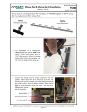
If sample is mixing poorly at one or a few positions, the mixing pads may not be making good contact with the bag and paddle behind it. Refer to TDF Service Procedure #10.

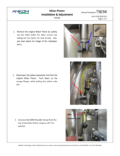
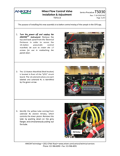
If sample is mixing poorly in general, an addition of flow control valves on the inrush and exhaust of nitrogen at the mixer piston will help.  These will be accessible from the rear of the instrument afford better mixing control.  Refer to TDF Service Procedure #30.  Also see link to part TDF113 Mixer Flow Control Valve Assembly.

Documents for This Question

Procedure Title Download
30 Mixer Flow Control Valve Installation and Adjustment View PDF
10 Mixing Pad Adjustment View PDF

The Waste Tray is leaking fluid at the Drain Tube Connection; what should I do?

Please click the "Tech Bulletin - TDF - Waste Tray Leak" link in the table below.

Documents for This Question

Procedure Title Download
Tech Bulletin - TDF - Waste Tray Leak View PDF

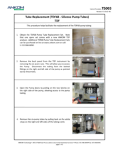
How do I change the Pump Tubing?

Refer to TDF Service Procedure #3 for instructions on changing the Pump Tubing.

How often should I change the TDF68 Silicone Pump Tubing?

The TDF68 Silicone Pump Tubing should be changed when the instrument prompts the user with an E13 warning for weak pump tubes. The pump tubes typically last 6 months under normal use.  Heavy usage may necessitate a more abbreviated time period between tubing changes.  

Email ANKOM Technology at [email protected] or call 315-986-8090 to purchase your Pump Tubing Replacement Kit (TDF68).

Refer to TDF Service Procedure #3 (TS003) for installation instructions.  

How often should I change the Enzyme Tubing?

The enzyme tubing should be changed once every two years under normal use. Heavy use may necessitate a more abbreviated time period between tubing changes.

Email ANKOM Technology at [email protected] or call 315-986-8090 to purchase your Enzyme Tubing Replacement Kit (TDF67).

Refer to TDF Service Procedure #4 for installation instructions.

Documents for This Question

Procedure Title Download
04 Tube Replacement (Enzymes) View PDF

What should I do if the Enzyme Pinch Valve is not working?

Following are two possible reasons why an Enzyme Pinch Valve may not be functioning properly.

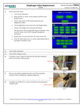
a. The silicone tubes may be worn or flattened from use. To inspect the tubing, refer to TDF Service Procedure #5 and reference the steps related to performing a "Valve Test." Perform the "Valve Test" and follow the proceeding steps to open the Enzyme Pinch Bar and examine the tubing. The silicone tubes should be intact, meaning that the tube passageways are clear and fully opening on their own. However, if any of the silicone tubes are excessively flattened or stuck in a pinched or closed position on their own (without the pistons pushing against them), then the tubes need to be replaced with the spare 3 1/4" silicone tubing that was originally sent with the TDF instrument. A set of 21 replacement tubes (3 1/4") can be ordered as TDF71 Pinch Valve Tubing Set.

b. The Enzyme Pinch Valve pistons may be stuck pinching the tubing closed. To inspect the pistons, refer to TDF Service Procedure #5 and reference the steps related to performing a "Valve Test" for each of the three enzymes. Perform the "Valve Test" and follow the proceeding steps to open the Enzyme Pinch Bar and observe the pistons. The three pistons should be properly retracted back inside each of the valves. If the pistons are protruding outward or pushing against the tubing, the Enzyme Pinch Valve Assembly may need to be replaced. Alternatively, there may be a problem with the solenoid that operates one or more of the pistons in the Enzyme Pinch Valve. Contact ANKOM Technology via e-mail at [email protected] or by calling 1-315-986-8090 for assistance in making this determination. If needed, follow TDF Service Procedure #9 to replace the entire Enzyme Pinch Valve Assembly.

Documents for This Question

Procedure Title Download
09 Pinch Valve Replacement (Enzymes) View PDF

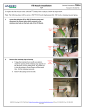
How do I replace a broken Fill Nozzle?

Refer to TDF Service Procedure # 14.

Documents for This Question

Procedure Title Download
14 Fill Nozzle Installation View PDF

What is the recommended maintenance for the TDF instrument?

Maintenance procedures are found under the section titled, "Periodic Maintenance" in your TDF Operator's Manual.

How much nitrogen is required for each TDF run?

A typical TDF run requires approx. 1400L (50cu.ft.) nitrogen gas. ANKOM recommends nitrogen gas be used versus compressed air due to the fact that nitrogen is generally cleaner, drier, and reduces fire risk associated with volatile solvents. The nitrogen supply should be 6.9 bar (100 psi). During the run, the nitrogen is used to operate pressure cylinders and also to facilitate bag filtering. During the filtering stage, the nitrogen is regulated to .3 bar (4 psi) and flow rate is approx. 15L/min  (.5cu.ft.).

How much bench space does the ANKOM TDF Dietary Fiber Analyzer require and how much does it weigh?

The TDF instrument requires the following bench space: 132 cm long (52") x 77cm deep (30") x 92 cm high (36"). 
For shipment, some parts are removed and the dimensions are: 107 cm long (42") x 51 cm deep (20") x 76 cm high (30").

The TDF instrument alone weighs about 65 Kgs (142 lbs).  With the controller, attachments and other spare parts the weight is about 71 kgs (157 Lbs). A rinse stand adds 2.75 kgs (6 lbs) to the shipping weight.  The total weight for shipping purposes, when the order includes a rinse stand, is 93.5 kgs (206 Lbs).

Is there a recommended procedure for storing the TDF Instrument during a period of non-use?

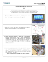
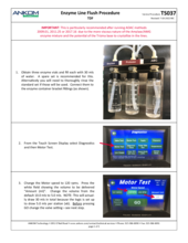
Yes, there is a recommended procedure for the TDF Instrument for periods of non-use.  Whenever the TDF Instrument is not being used for one week or longer, run the Line Flush and Purge Procedure (as detailed in TDF Service Procedure #15). Following this procedure will help maintain clear fluid lines.


Documents for This Question

Procedure Title Download
15 Line Flush and Purge Procedure View PDF

Are there any special instructions for the return of a TDF Analyzer for service?

Yes. Please refer to TDF Service Procedure #19 for details on how to ship your TDF Analyzer to ANKOM Technology.

Documents for This Question

Procedure Title Download
19 Return Shipping Instructions View PDF

What is the recommended maintenance for the TDF instrument?

Documents for This Question

Procedure Title Download
TDF Maintenance Checklist View PDF

What is the difference between IDF and SDF filter bags?

IDF filter bags have a shorter length of clear polypropylene material and a taller filter at the bottom of the bag.

SDF filter bags have a longer length of clear polypropylene material and a shorter, wider filter at the bottom of the bag.

What is the bag weighing procedure?

Refer to the TDF Operator's Manual, sections "IDF/SDF Analysis" and "TDF Analysis."

How should I de-fat samples when using the ANKOM automated TDF instrument?

With regard to sample fat content, AOAC 985.29 (the first dietary fiber method) says:

“If high fat content (>10%) prevents proper milling, defat with petroleum ether (3 times with 25 ml portions/g sample) before milling.  Record loss of weight due to fat removal and make appropriate correction to final % dietary fiber found in determination.” 


The other AOAC Dietary Fiber procedures that followed 985.29 refer to 985.29 for sample prep.  The method only speaks about samples that can’t be ground due to the high fat content.  There is no mention of the high fat content interfering with the fiber process. 
 
With that said, we recognize that most labs perform a de-fatting step on all high fat samples and we are not aware of any research to indicate an effect or lack thereof on the fiber process. 
 
Should you choose to perform the de-fatting step on your samples, page 93 of our Operator’s Manual shows the simple method we have developed for this procedure.  You can also click this link to view a video describing the procedure.

Documents for This Question

Procedure Title Download
TDF Dietary Fiber Analyzer Operator's Manual View PDF

What are the procedures for inserting sample and Diatomaceous Earth into the filter bags?

Refer to the TDF Operator's Manual, sections "IDF/SDF Analysis" and "TDF Analysis."

How do I perform a pH adjustment during the IDF phase?

Follow the steps in this instructional video to perform a pH adjustment: TDF Manually Measuring pH in the IDF Digestion

Note: Measure within the appropriate pH range for your specific testing method.

What can cause HIGHER than expected Dietary Fiber results?

Static electricity during the weighting process:  The largest contributor to poor results is the effect of static electricity on the weighing process. Because plastic gloves can contribute to static electricity, only use anti-static gloves. To eliminate static electricity while the bag is being weighed, you MUST use the Bag Weigh Holder (TDF52) during the weighing process.

Moisture control: Moisture Stop desiccant pouches (X45) should be used to minimize the effect of moisture on the weighing process. Verify that the desiccant pouches are in good condition (no holes and the zipper is functioning) and the packets within the desiccant pouches are still working (they should be a blue color).

BLANK values: BLANK values are used in the IDF, SDF, and TDF calculations. If you're not using the BLANK values provided by ANKOM, try using them in your calculation.

Chemicals: Because the MES-TRIS buffer can degrade in performance due to bacteria growth, making this solution daily is important. Clean all containers daily and refill with fresh solutions. Make sure that each container is securely connected to the appropriate supply tube on the instrument.

Protein and Ash Determinations: Because protein and ash values are part of the IDF, SDF, and TDF calculations, verify that your protein and ash systems are working properly and providing expected results.

Protein and Ash preparation: See the procedures detailed in the TDF Operator's Manual (Protein and Ash Determination sections) for preparing the bags for protein and ash.

Drying: Bags must be dried at 105° C to constant weight (90 minutes).

Acetone rinses: See the procedure detailed in the TDF Operator's Manual (IDF/SDF Analysis section) for performing the acetone rinses.

Sample size: Using sample sizes larger than the recommended size of 0.5 (+/- 0.05g) can cause higher results.

Digestion times: For demonstration and diagnostic purposes, you can set the digestion times to non-standard values through the Touch Screen Display. Results will be inaccurate if the instrument is run using non-standard digestion times.

Technician variability: Confirm that all technicians are following the procedures detailed in the TDF Operator's Manual to avoid any variation in results associated with different operators.

pH: Typically the pH reading should be between 3.5 and 6 before correction. If the pH reading is outside of these values check the acid and buffer solutions, and check that tubing is connected to the proper containers.

Enzyme delivery: View the enzyme containers while the enzymes are being delivered. The fluid level should go down. If the enzymes are not being delivered properly, contact ANKOM at [email protected].

Temperature control: To verify that the temperature is being properly controlled, follow the procedure detailed in the TDF Operator's Manual (QC / Calibration section).

Mixing: To verify that the mixing is being properly controlled, follow the procedure detailed in the TDF Operator's Manual (QC / Calibration section).

What can cause LOWER than expected Dietary Fiber results?

Static electricity during the weighting process:  The largest contributor to poor results is the effect of static electricity on the weighing process. Because plastic gloves can contribute to static electricity, only use anti-static gloves. To eliminate static electricity while the bag is being weighed, you MUST use the Bag Weigh Holder (TDF52) during the weighing process.

Sample sticking to the IDF Flow-thru bags: When running a TDF assay, particles can stick to the IDF Flow-thru bag and not get rinsed down into the SDF filter. The weight of the sample stuck to the IDF Flow-thru bag is not accounted for in the TDF calculation. To avoid this problem, after the digestion processes are complete, use 78% EtOH to manually rinse any sticky particles down from the IDF Flow-thru bag into the SDF bag. If necessary, a laboratory spatula can be used to help loosen particles that are stuck to the bag.

BLANK values: BLANK values are used in the IDF, SDF, and TDF calculations. If you're not using the BLANK values provided by ANKOM, try using them in your calculation.

Chemicals: Because the MES-TRIS buffer can degrade in performance due to bacteria growth, making this solution daily is important. Clean all containers daily and refill with fresh solutions. Make sure that each container is securely connected to the appropriate supply tube on the instrument.

Protein and Ash Determinations: Because protein and ash values are part of the IDF, SDF, and TDF calculations, verify that your protein and ash systems are working properly and providing expected results.

Protein and Ash preparation: See the procedures detailed in the TDF Operator's Manual (Protein and Ash Determination sections) for preparing the bags for protein and ash.

Drying: Bags must be dried at 105°C to constant weight (90 minutes).

Acetone rinses: See the procedure detailed in the (IDF/SDF Analysis section) for performing the acetone rinses. TDF Operator's Manual

Sample loss: If any sample is spilled or left in a weigh tin during transfer to the IDF bag, the assay will produce lower values.

Filtrate transfer from IDF to SDF bag: If any liquid does not quantitatively transfer from the IDF bag to the SDF bag, SDF results will be low. Make sure that the bottom of the IDF bags remain inside the top of the SDF bags during the IDF filter process.

Diatomaceous Earth (DE) loss: If any DE is spilled or left in a weigh tin during transfer to the SDF bag, the assay will produce lower values.

Digestion times: For demonstration and diagnostic purposes, you can set the digestion times to non-standard values through the Touch Screen Display. Results will be inaccurate if the instrument is run using non-standard digestion times.

Technician variability: Confirm that all technicians are following the procedures detailed in the TDF Operator's Manual to avoid any variation in results associated with different operators.

pH: Typically the pH reading should be between 3.5 and 6 before correction. If the pH reading is outside of these values check the acid and buffer solutions, and check that tubing is connected to the proper containers.

What is a MoistureStop Desiccant Pouch, how is it used, and why should I use it?

The MoistureStop Desiccant Pouch is a small, airtight zipper bag, utilized for desiccating all of the Filter Bags that are used with ANKOM instrumentation. A single pouch can hold a full run of F57, F58 or XT4 bags at one time.  When folded, 6 IDF or SDF bags can also be placed into a MoistureStop Desiccant Pouch. Each time a bag has been removed from the desiccant pouch, the air can and should be pushed out. The "zipper" does not have to be used with every bag removal but some action should be taken to keep the air from entering the pouch while the just removed Filter Bag is being weighed. For example, air can be pushed out of the bag by laying it on a firm surface while compressing or flattening the air out of the pouch with your hand.

Many instruments in the marketplace have the capacity to run 6 samples at a time.  After being dried, the beakers, flasks or crucibles are placed into a counter top or cabinet desiccator.  Once cooled, they are then removed one at a time and weighed. Each time the desiccator is opened to remove sample, moist ambient air is introduced inside the desiccator. However, because the lid or door of the desiccator is opened just 6 times, the samples that remain in the desiccator after each item is removed are affected very little by ambient moisture that may be introduced.

However, with Filter Bag Technology, generally larger numbers of Filter Bags are extracted at a time. As with the beakers, flasks and crucibles mentioned above, if the bags are placed in a desiccator after drying, each time the lid or door is opened to remove a bag, moist, ambient air is introduced. Because the desiccator is opened up to 24 times, the moisture can more readily affect the remaining bags. If a collapsible, ANKOM desiccant pouch is utilized, the air can be pushed out of the pouch each time a Filter Bag is removed. This will eliminate a build up of moisture on the remaining Filter Bags and allow for a more accurate and precise result. Every month it is possible to place the small desiccant packets into the oven at 100° - 105 ° C for a few hours to insure that the desiccant is renewed. In addition, to ensure the integrity of the zip lock bag, regular replacement should be considered.

How do I prepare bags for Kjeldahl & Ashing procedures?

In order to properly prepare the IDF & SDF bags for Kjeldahl and Ashing procedures, view the documents below or watch the following video: Kjeldahl & Ashing Bag Preparation.

Documents for This Question

Procedure Title Download
Ash Procedure (IDF, SDF, TDF) View PDF

What times and temperatures should I set on my Kjeldahl to determine the protein in the IDF/SDF filter bags?

We have found that it is best to slowly ramp up the digestion temperatures so that foaming in the digestion tubes is minimized. As a result we would suggest the following times and temperatures: 15 minutes at 150°C followed by 15 minutes at 250°C followed by 15 minutes at 350°C and finally 40 minutes at 420°C.

How do I analyze liquid samples in the TDF Analyzer?

Utilize a transfer pipette to handle this and follow the procedure below:
  1. Weigh the pipette and tare the weight.
  2. Fill the pipette with a liquid sample.
  3. Place the pipette on the balance and record the weight.
  4. Pipette out the liquid into the IDF Bag.
  5. Weigh the pipette and subtract that weight from the weight with a sample. This supplies us with the actual sample weight that went into the bag.

How do I handle samples that are difficult to filter?

The IDF and SDF filter bags have a significantly greater filter surface area than is found in the Gooch filter-crucible. However, regardless of filter surface area, some sample types can be difficult to filter. Samples that become quite gelatinous in an aqueous solution (such as psyllium and chia seeds) can be difficult to filter.  To accommodate these types of samples in the ANKOMTDF Dietary Fiber Analyzer we recommend the following options:

Add filter time before the assay begins
At the beginning of a run a series of user prompts appear on screen, one of which states, “Filter Minutes OK? (for an IDF/SDF run) or “SDF Filter minutes OK?” for a TDF run.  From this screen, you can add filter time if you are working with samples that require more filter time.  Familiarity with a particular sample may dictate 10 minutes of IDF filter time, for example. Be aware that any time changes will be stored to memory and will be there for the next run.  You will, however, be able to change this back to the default or another setting at the beginning of each run.

Add more filter time during the filtering process
During IDF or SDF filtration and during the water or alcohol rinses (when filtering is occurring) one can press the “Filter Time +” button to add one additional minute at a time, up to 50 additional minutes.  The user will need to be present at the time of filtering to take advantage of this option.

Use a smaller sample size
Reduce the sample size to 0.1 g to minimize the filter clogging effect of gelatinous sample types.

Use Diatomaceous Earth (DE) in the IDF bags 
Pre-weigh 1 g of DE for each IDF bag.  When starting the run, select YES for the screen that states, “Check pH manually?”. Select YES whether or not you plan to perform a manual pH check.  When the instrument pauses for the pH check (and after any pH check/adjustment is complete) add 1 g of DE to each bag.  Press the “Continue” button once DE is added. The DE will be mixed in during the AMG digestion.  Adding the DE at this point, rather than at the beginning of the run, minimizes the risk of bag wear during mixing by having abrasive DE in a hot bag.  Be sure that the DE in the IDF bags is factored into your blank values.  Use of this technique helps increase filter capacity.

What are the filtration specifications for the ANKOM TDF filtration process?

AOAC 991.43 calls for filtration via a fritted crucible of 40-60 microns with diatomaceous earth, or equivalent.  Particle retention per the method is accomplished by the addition of diatomaceous earth contained in a fritted crucible.  The fine filtration and particle retention of the ANKOM SDF bags is also accomplished with diatomaceous earth contained in the filter bag.  The IDF filtration may or may not use the diatomaceous earth but produces the correct particle retention in a water medium.  Therefore, the filtration used in the ANKOM TDF is equivalent to the approved AOAC 991.43 Method.

Parts & Ancillary Products

TDF Analyzer
Link here to access a full list of parts and ancillary products for the TDF Fiber Analyzer.
Parts List

Related Links

Contact Information
Global Distribution Map
Warranty Information

Videos

Automated Dietary Fiber Analysis

Automated Dietary Fiber Analysis


arrow-white-footer.pngHave Questions or Feedback?
Connect
Follow us on TwitterFind us on FacebookConnect with us on LinkedIN

Menu

  • Product Catalog
  • Technical Support
  • Analytical Methods & Support
  • Case Studies
  • Global Distribution

ANKOM Technology

©2019 ANKOM Technology All Rights Reserved
ANKOM Technology 2052 O'Neil Road, Macedon NY 14502
Tel: 315.986.8090 | Fax: 315.986.8091