TDF Support
Manuals & Methods
Top Five FAQs
The touchscreen display will give you the option to Retry, Override, or Abort the run.
Retry will simply try the delivery again. Override will ignore the fault for the remainder of the run. Abort will stop the run entirely.
To analyze the problem, do the following:
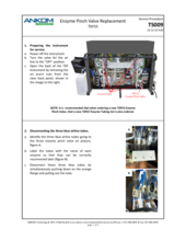
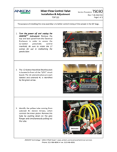
When the instrument is not in the process of running an analysis, an E15 fault can be investigated by performing a Motor Test under Diagnostics. From the Motor Test screen, press Set Valves and select the valve that caused the fault. If this is not known, test each supply valve. Open only one supply valve at a time and close all others. Open the Waste output valve and close the IDF and SDF output valves. Be sure that there is adequate fluid in the reservoir that is being tested. Change the delivery volume to 20 ml and press GO. Watch the vacuum reading on the screen. Typical readings are between 0.7 – 1.5 psi. A reading above 3 psi will generate an E15 fault (during a run). If one of the supply lines shows a high reading, you have isolated the supply line that is causing the problem.
Possible causes of an E15 fault include:
(1) Clogged Filter
The most likely cause of an E15 fault at the Water, Buffer, EtOH 78, EtOH 95 or HCl lines is a clogged filter. Severely clogged filters may reduce delivery volumes and affect results. The filters are at the end of the draw tubes inside the containers. These should be checked monthly and cleaned as needed. The filters can usually be cleaned with a soft bristle brush under running water. If they can't be cleaned, there are two spares of the plastic-type container filters (used for water, alcohols, and HCl/Acetic Acid) and one spare of the metal screen filters (used for buffer) included with the instrument on the original purchase. Additional ones may be ordered as Container Filter (Part #: 8202) and Buffer Filter (Part #: 8203).
(2) Quick Disconnect Fitting not fully locked in place
A quick disconnect fitting functions as a valve that closes when disconnected or not fully connected. Quick disconnect fittings are found at the following reservoirs: enzymes, water, and alcohols. Check to make sure that they cannot be pulled out without pressing the release button. If they can be pulled out without the use of the release button, they are not fully engaged, and fluids will not be drawn. Push them into the adjoining fitting until you hear them snap in place. Confirm that they cannot be pulled out. It is also possible that the fittings may need to be replaced. The fittings needed are Coupling Body (Part #: 8193) and Coupling Insert (Part #: 8149) available on our website.
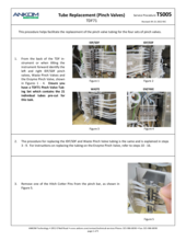
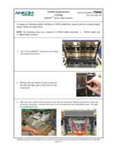
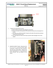
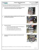
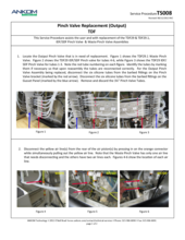
(3) Worn tubing in the Enzyme Pinch Valve
An E15 fault at one of the Enzyme lines (Amylase, Protease, or AMG) could be due to worn tubing in the Enzyme Pinch Valve. As the tubing in the Enzyme Pinch Valve ages, it may become stuck closed preventing the flow of enzymes. Refer to and follow TDF Service Procedure Tube Replacement Enzymes (TS004), first replacing the tubing within the Pinch Valve. These tubes should be replaced annually. Spare Pinch Valve tubing comes with the TDF instrument upon original purchase; additional tubing can be ordered as a Pinch Valve Tubing Set (21 pcs) (Part #: TDF71). Also, inspect the supply lines to see if there is a clog or pinch in the line. These also may require replacement. A set of all enzyme tubes, the Enyzme Tubing Replacement Kit (Part#: TDF67) is available for purchase. If the problem persists, contact ANKOM Technology at https://www.ankom.com/contact/technical-services or (315) 986-8090 for further assistance.
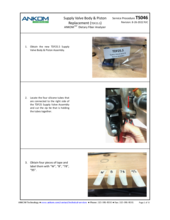
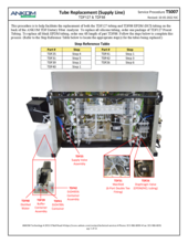
(4) Pinched or plugged Supply Line or a faulty Supply Valve
Other possible causes for an E15 fault are a pinched or plugged Supply Line or a faulty Supply Valve. Inspect the supply line in question to see if such a problem can be seen visually. After having cleaned and/or replaced the filter and having checked for fully engaged disconnect fittings, if the problem persists, contact ANKOM Technology at https://www.ankom.com/contact/technical-services or (315) 986-8090 for further assistance.
IMPORTANT: This message can be falsely declared if your instrument has been idle for a period of time. To reduce the chance of false declarations always run a line charge or two at the beginning of a routine, especially after a period of idle time (e.g., after a weekend or a long holiday).
The ALERT message “Tube (X) weak. Tubing replacement recommended” is due to one or more of the pump tubes giving a low-pressure reading during the testing of the pump tubes at the start of the analysis. When the message is presented as an ALERT the problem can be ignored temporarily and addressed after the analysis is complete (Do not repeatedly ignore this message or you risk the pump tubes breaking and causing corrosion within the peristaltic pump). If the holding pressure of the pump tubes was very poor, you would see an E13 Pump Tube Failure message. This ALERT is cautioning you that the pump tubes are not holding pressure well. It is possible though that if the tubing is dry (e.g. if the instrument has been idle for a week) and if the lines have not been fully charged with the solutions the air in the lines can cause a weak tube message.
To diagnose the cause, follow these steps:
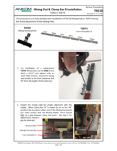
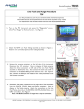
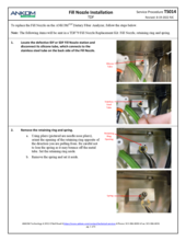
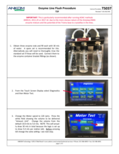
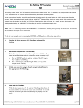
(1) Connect the Flush Tube Assembly (Part #: TDF70) to all of the supply ports with the middle connector attached to the water container.
(2) In the Diagnostics menu, run a Line Charge (ALL) several times to ensure the lines are filled with water.
(3) Run a Pump Tube Test, also found in Diagnostics.
This will display pressure results for each of the 6 pump tubes. The minimum to PASS is a reading of at or above 8 psi. If the results are between 5.0 – 7.9 psi you will see a WARNING. If the results are less than 5.0 psi the test will display FAIL. Running this test in Diagnostics will confirm the problem or show that it is corrected with proper charging of the lines.
(4) If the Pump Tube Test failed...
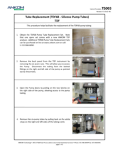
If the instrument fails the Pump Tube Test, generally the solution is to replace the pump tubes, but there can be other causes as described in TDF Service Procedure E13 Diagnosis. Depending on the software on your instrument, you would need either #TDF68 Silicone Pump Tubes (software version 3.60 or earlier) or #TDF99 Pump Tubes (software version 3.70 or later).
For more information on the weak tubes alert, see Service Procedure E13 Fault Diagnosis (TS001). For installation procedures, refer to TDF Service Procedure Silicone Pump Tube Replacement for TDF68 (TS003) and TDF Service Procedure Long-Life Pump Tube Replacement (TS028) for TDF99 to confirm the reason. If the instrument fails the Pump Tube Test, generally the solution is to replace the pump tubes, but there can be other causes as described in the Pump Tube Replacement Service Procedure.
Refer to TDF Service Procedure E13 Diagnosis (TS001) to diagnose tubing pressure failure.
Static electricity during the weighting process: The largest contributor to poor results is the effect of static electricity on the weighing process. Because plastic gloves can contribute to static electricity, only use anti-static gloves. To eliminate static electricity while the bag is being weighed, you MUST use the Bag Weigh Holder (Part #: TDF52) during the weighing process.
Moisture control: The MoistureStop Desiccant Pouches (Part #: X45) should be used to minimize the effect of moisture on the weighing process. Verify that the desiccant pouches are in good condition (no holes and the zipper is functioning) and the packets within the desiccant pouches are still working (they should be a blue color).
BLANK values: BLANK values are used in the IDF, SDF, and TDF calculations. If you're not using the BLANK values provided by ANKOM, try using them in your calculation.
Chemicals: Because the MES-TRIS buffer can degrade in performance due to bacteria growth, making this solution daily is important. Clean all containers daily and refill them with fresh solutions. Make sure that each container is securely connected to the appropriate supply tube on the instrument.
Protein and Ash Determinations: Because protein and ash values are part of the IDF, SDF, and TDF calculations, verify that your protein and ash systems are working properly and providing the expected results.
Protein and Ash Preparation: See the procedures detailed in the TDF Operator's Manual (Ash Determination section) for preparing the bags for ashing. To prepare the ANKOM Filter Bags for protein analysis via Kjeldahl, refer to the TDF Operator’s Manual.
To prepare the ANKOM Filter Bags for analysis via combustion methods, cut open the Filter Bag and lightly scrape or brush the particles of sample residue and DE into a small mortar. Grind the mixture with the pestle until homogenous. Take several aliquots of the mixture and run them through your dumas. Use the average protein value of the aliquots for the TDF calculation.
Various manufacturer options are available for nitrogen determination using the combustion method. Contact your combustion/dumas manufacturer for further information regarding specific settings and recommendations regarding N2 determinations that involve DE.
Drying: Bags must be dried at 105° C to constant weight (90 minutes).
Acetone rinses: See the procedure detailed in the TDF Operator's Manual (IDF/SDF Analysis section) for performing the acetone rinses.
Sample size: Using sample sizes larger than the recommended size can cause higher results. ANKOM recommends using a sample size of 0.5 g (+ / - 0.05g) however a larger sample up to 1g is acceptable.
Digestion times: For demonstration and diagnostic purposes, you can set the digestion times to non-standard values through the Touch Screen Display. Results will be inaccurate if the instrument is run using non-standard digestion times.
Technician variability: Confirm that all technicians are following the procedures detailed in the TDF Operator's Manual to avoid any variation in results associated with different operators.
pH: Typically, the pH reading should be between 3.5 and 6 before correction. If the pH reading is outside of these values check the acid and buffer solutions, and check that tubing is connected to the proper containers.
Enzyme delivery: View the enzyme containers while the enzymes are being delivered. The fluid level should go down. If the enzymes are not being delivered properly, contact ANKOM at https://www.ankom.com/contact/technical-services or (315) 986-8090.
Temperature control: To verify that the temperature is being properly controlled, follow the procedure detailed in the TDF Operator's Manual (QC / Calibration section).
Mixing: To verify that the mixing is being properly controlled, follow the procedure detailed in the TDF Operator's Manual (QC / Calibration section).
Sample with bound fat: It is possible you have a sample that is highly processed and has bound the fat to the extent the fat is not available to the solvent before the TDF process. In this case, after running the TDF instrument, remove the bags, place them on the rinse stand, and perform the two standard acetone rinses. Immediately after the rinses (no air drying), remove the bags from the stand and soak the filters in fresh pet ether for ten minutes. Place the bags back on the rinse stand and immediately perform two pet ether rinses (just like the acetone rinses). When the solvent has evaporated, seal the bags and dry them normally.
Static electricity during the weighting process: The largest contributor to poor results is the effect of static electricity on the weighing process. Because plastic gloves can contribute to static electricity, only use anti-static gloves. To eliminate static electricity while the bag is being weighed, you MUST use the Bag Weigh Holder (Part #: TDF52) during the weighing process.
Sample sticking to the IDF Flow-thru bags: When running a TDF assay, particles can stick to the IDF Flow-thru bag and not get rinsed down into the SDF filter. The weight of the sample stuck to the IDF Flow-thru bag is not accounted for in the TDF calculation. To avoid this problem, after the digestion processes are complete, use 78% EtOH to manually rinse any sticky particles down from the IDF Flow-thru bag into the SDF bag. If necessary, a laboratory spatula can be used to help loosen particles that are stuck to the bag.
BLANK values: BLANK values are used in the IDF, SDF, and TDF calculations. If you're not using the BLANK values provided by ANKOM, try using them in your calculation.
Chemicals: Because the MES-TRIS buffer can degrade in performance due to bacteria growth, making this solution daily is important. Clean all containers daily and refill them with fresh solutions. Make sure that each container is securely connected to the appropriate supply tube on the instrument.
Protein and Ash Determinations: Because protein and ash values are part of the IDF, SDF, and TDF calculations, verify that your protein and ash systems are working properly and providing the expected results.
Protein and Ash preparation: See the procedures detailed in the TDF Operator's Manual (Protein and Ash Determination sections) for preparing the bags for protein and ash.
Drying: Bags must be dried at 105°C to constant weight (90 minutes).
Acetone rinses: See the procedure detailed in the (IDF/SDF Analysis section) for performing the acetone rinses in the TDF Operator's Manual.
Sample loss: If any sample is spilled or left in a weigh tin during transfer to the IDF bag, the assay will produce lower values.
Filtrate transfer from IDF to SDF bag: If any liquid does not quantitatively transfer from the IDF bag to the SDF bag, SDF results will be low. Make sure that the bottom of the IDF bags remain inside the top of the SDF bags during the IDF filter process.
Diatomaceous Earth (DE) loss: If any DE is spilled or left in a weigh tin during transfer to the SDF bag, the assay will produce lower values.
Digestion times: For demonstration and diagnostic purposes, you can set the digestion times to non-standard values through the Touch Screen Display. Results will be inaccurate if the instrument is run using non-standard digestion times.
Technician variability: Confirm that all technicians are following the procedures detailed in the TDF Operator's Manual to avoid any variation in results associated with different operators.
pH: Typically, the pH reading should be between 3.5 and 6 before correction. If the pH reading is outside of these values check the acid and buffer solutions, and check that tubing is connected to the proper containers.
Troubleshooting? Let us help!
For the most efficient and quick way to determine what your instrument issue is, it is important to fill out the diagnostic questionnaire below and submit to our analytical service form. Our team will review and get back to you with help!
Parts & Consumables
Browse the TDF Product Catalog for associated parts and support items
Preventative Maintenance Kit
Essential items needed to keep your instrument operating smoothly
Instrument Performance Test
Check samples ensure proper instrument function and correct procedural technique.
SDS Sheets
View associated product documentation and safety information

Service Procedures


How can we help?
Don’t see what you need on this page?
Search for a specific topic to browse all resources.